DJ-1000 HV Cable On-line Monitoring and Fault Location System
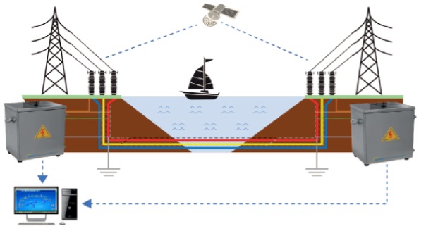
The use of cables on transmission systems is becoming increasingly common, which can make the location of faults on the system difficult to locate. The DJ-1000 uses travelling wave technology, coupled with an extremely high sampling rate, to provide an accurate fault location. The system is also capable of identifying and locating sheath faults and monitoring the load. It is applicable to HV AC cables, including underground, underwater and hybrid systems.
Features
- High performance capture of travelling wave signals for fault location.
- Samples at 50MHz per channel, with a fault location resolution of less than 4m.
- High precision GPS time synchronization with a 20ηs accuracy.
- High fidelity reproduction of travelling wave signals.
- Fundamental frequency current measurement, for load monitoring faulty section identification using the current differential principle.
- Sheath fault detection using sensitive currents measurement.
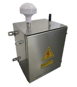
- Indoor and outdoor, non-intrusive installation.
- AC mains powered, solar-powered and/or self-powered by the phase current.
- Communications to the master station through the 4G/5G mobile network
System Description
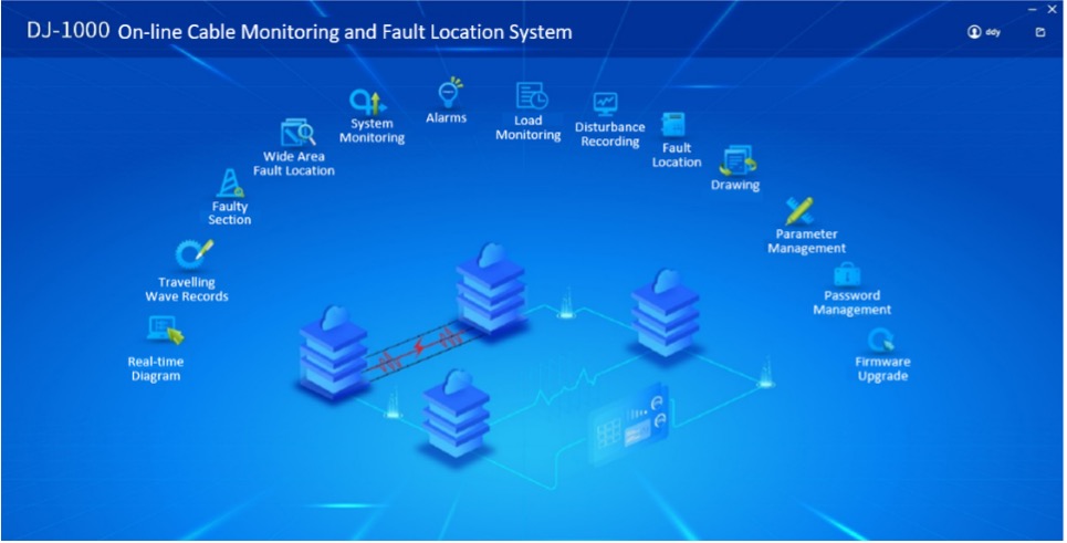
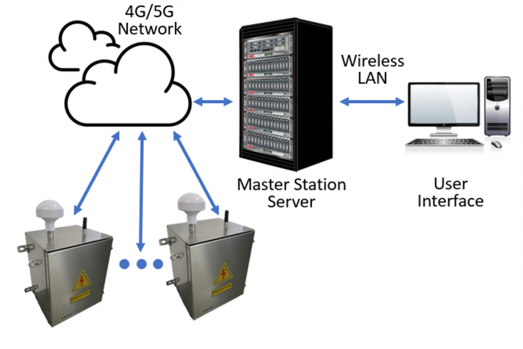
The DJ-1000 HV cable monitoring and fault location system consists of a number of DJ-100 devices, a master station and accessories including sensors, GPS antennae optional solar panels etc. The master station communicates with the DJ-100 devices in the field, through the 4G/5G mobile network. It performs fault location calculations, on-line load monitoring and data analysis for the cable network. The home page of the Master station is shown below:
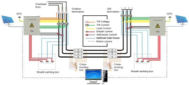
The diagram shows the interfaces of a typical system between an outdoor cable and overhead line terminal and an indoor GIS cable terminal. CTs monitor the power system frequency load, sheath and earth currents, whilst high frequency sensors look for the arrival of current and/or voltage travelling waves. The system is powered from CTs around phases of the cable, or it can be solar powered.
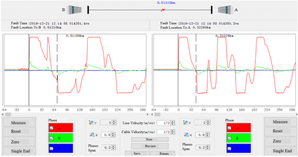
The DL-1000 system uses the well-established single and double-ended travelling wave fault location principles to determine the distance to the fault. Six analogue channels are used to capture the high frequency travelling waves from the three phase voltages and currents. The 50MHz sampling rate, coupled with the 20ηs high precision GPS clock, result in a fault location resolution of 4m. Custom-built wide-bandwidth voltage and current sensors minimise the rise time of the signal. Triggers can be achieved very close to the fault inception, thus further enhancing the accuracy of the fault location. When a fault has occurred and the DL-100s at the ends of the cable section have triggered, the precise time-tags of the trigger and the travelling wave waveforms are sent to the master station which makes the fault location calculations, with the results provided on the user interface (below).
 </
</
Load Monitoring & Faulty Section Identification
Three analogue channels are dedicated to monitoring the fundamental frequency 3-phase currents, with a sampling rate of 6.4kHz. They are used for continuous load monitoring and disturbance recording. Each trigger produces a disturbance record of 0.5s duration, which can be used to assess the cause of a fault. The data from the DL-1000s at different nodes are time-synchronised thorough GPS, therefore current differential protection principle can be applied by the master station to identify the cable section where the fault occurred.
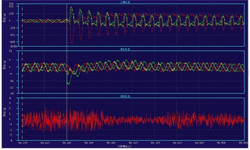
Load Current record
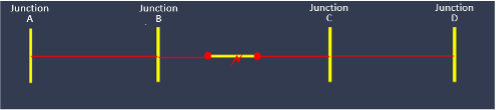
Faulted section indication
Sheath Fault Detection
Four analogue channels are dedicated to monitor the 3-phase sheath currents plus their summated current, with a sampling rate of 6.4kHz. The nominal sheath currents under healthy conditions, are just a few amperes. Excessive sheath current indicates there is an abnormality and the ratio of sheath current to the load current is used for fault detection. If the ratio is above a settable threshold, there will be an alarm and a disturbance record will be taken. The summated current eliminates the balanced nominal sheath currents and provides an additional measurement to indicate a load imbalance.
| DJ-1000 Technical data | |
| Travelling Wave Fault Location | |
| Number of travelling wave analogue channels | 3 (phase currents) + 3 (phase voltages) |
| Travelling wave sampling frequency | 50MHz |
| GPS timing accuracy | 20ηs |
| Fault location resolution | 4m |
| Number of power frequency analogue channels | 3 (phase currents) + 3 (sheath currents) |
| Power frequency sampling frequency | 6.2KHz |
| Power frequency disturbance record length | 500ms |
| Travelling wave sensors (voltage and current) | |
| Measurement accuracy | 5% |
| Measurement bandwidth | 1kHz to 10MHz |
| Cable operating voltage range | 100V to 500kV |
| Measuring range (Current sensor) | 10mA to 1000A |
| Installation method (voltage sensor) | Outdoor overhead line to cable terminals |
| Installation method (Current sensor) | Clip-on CT, indoor or outdoor installation |
| Current sensor internal diameter | 60mm |
| Load current sensor | |
| Measurement accuracy | 1% |
| Measurement bandwidth | 20Hz to 100Hz |
| Measuring range | 10A to 5000A |
| Installation method | Clip-on CT, indoor or outdoor installation |
| Load sensor internal diameter | 200mm |
| Sheath current sensor | |
| Measurement accuracy | 0.5% |
| Measuring range | 0 to 300A |
| Installation method | Clip-on CT, indoor or outdoor installation |
| Sheath current sensor internal diameter | 60mm |
| Power Supply | |
| Mains power supply | AC 220V ± 20% |
| Power from cable load; current range | 30A to 1000A |
| Power from cable load; Installation method | Clip-on CT, indoor or outdoor installation |
| Solar panel | 18V, 180W |
| Battery (2 sets) for solar power back-up | 12V 20AH (40AH total) lithium-ion |
| Environmental | |
| Maximum temperature | -20oC to 70oC |
| Humidity | 5% to 95%RH |
| Altitude | ≤3000m |
| Atmospheric pressure | 80 kPa to 106kPa |
| Insulation withstand level | DC 10kV/1min |
| Ingress protection | IP54 |
| Physical characteristics | |
| Dimensions (main unit) | 350 x 300 x 430mm |
| Weight (main unit) | 34Kg |
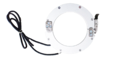
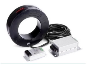
Sensors
 |
 |
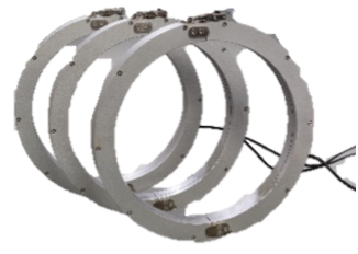 |
| Travelling wave voltage sensor | Travelling wave current sensor | Load current sensors |
 |
 |
|
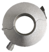
| Sheath current sensor | AC Power coupling CT |
Dimensions and Connections
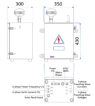
Scope of supply:
- DJ-100 HV cable monitoring and fault location device
- 3-phase power system frequency current sensors
- 3-phase travelling current sensors
- 3-phase travel wave voltage sensors (optional)
- 3-phase + residual sheath current sensors
- Solar panel (optional)
- AC power coupling CT (optional)
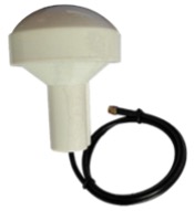
- GPS antenna
- Service manual
- Master station software