T-H300 Sheath Fault Locator
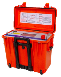
The T-H300 provides accurate automatic or manual fault location for cable sheath faults. It utilises either the DC resistance method or it can act as a bridge, in conjunction with an internal 12kV DC voltage source. The device can be used in automatic mode, providing accurate fault location based on only entering the cable length, or manual mode is also available. The equipment also allows the measurement of insulation impedance and, together with the separately available T-KF200, can provide fault pinpointing
The device main menu is shown below:
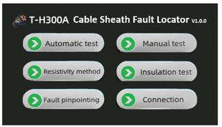
The main menu interface is divided into six sections: Automatic test, Manual test, Resistivity method, Insulation test, Fault pinpointing, and Connection.
- Automatic test: A one-key press automatic test, with options for the resistance method and the bridge method.
- Manual test: Manual control of the high-voltage output
- Resistivity method: This allows the resistivity of the cable to be measured
- Insulation test: Provides a test of the cable insulation, providing four test voltages (0.5kV, 1kV, 2.5kV and 5kV).
- Fault pinpointing: This function offers three modes:
- Single mode:.
- Cyclic mode:
- DC mode:
- Connection: This gives wiring diagrams for the different test methods.
Cables
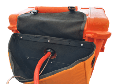
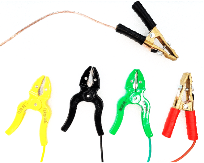
The rear of the T-H300A features a cable and accessory bag. The picture shows the working ground and the high voltage cable. These cables are 3.5m long and are fitted with heavy-duty crocodile clips.
Connectors
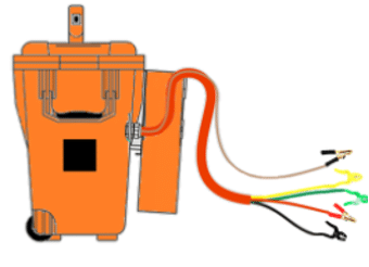
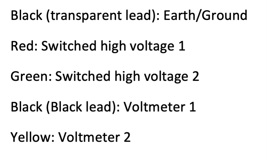
Figure 5.4 – T-H300A showing the HV cable and t
DC resistance method of sheath fault location
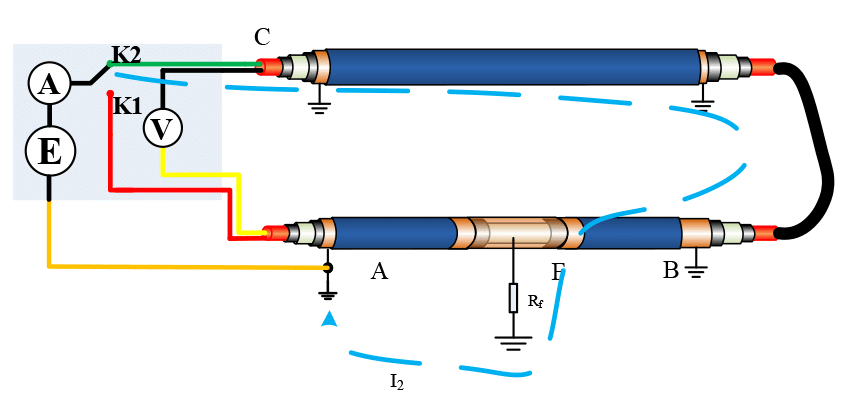
For this method, the faulty cable shield is connected to two healthy cores or healthy shields at the remote end. The benefit of this approach is that the shorting leads at the remote end are not part of the measurement circuit and so compromised connections will not adversely affect the measurement.
The DC resistance method calculates the fault distance by measuring the DC resistance from the measuring point to the fault point, initially along the faulty cable and then through a parallel cable attached at the remote end to the far end of the faulty cable. The other healthy phase is used to allow the voltmeter to be connected, such that it measures the voltage across the length of the cable plus the section of the faulty cable between the fault point and the far end. This arrangement is such that there is no need to reconnect the voltmeter the second part of the test.
Full length = L
First step:
I1 path :A→F then come back through earth
U1=UAF,R1=RAF
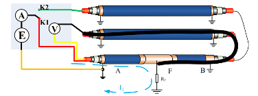
Second step: I2 path:C → B→ F then come back through earth
U2=UBF,R1+R2=RL
Fault distance=R1/(R1+R2).L
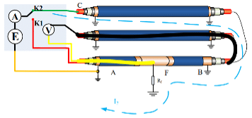
The terminal short circuit wire serves only as an extension for voltage measurement (shown in black and yellow) and is not within the measurement circuit itself, thus eliminating these wires from the measurement circuit.
Modified Bridge
The T-H300 does not use a traditional Murray loop approach to calculate the distance to the fault position.
The T-H300 takes a different approach to the bridge. Instead of comparing an external resistance to the resistances of the faulty core or sheath, it directly measures the resistances by applying a voltage source across the near end of the faulty cable and measuring the relevant voltages and currents.
Full length = L
First step:
I1 path :A→F then come back through earth
U1=UAF,R1=RAF
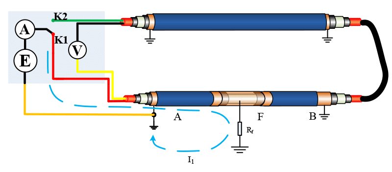
Second step:
I2 path:C → B→ F then come back through earth
U2=UCF,R2=RL+RBF
| Fault distance = | 2.R1.L |
| (R1+R2)
|
This emulates the equation from a traditional Murray Loop
Technical Data
| Output voltage | 0 -12kV |
| Output current | 0 – 50mA |
| Current Measuring range | 0 – 50mA, resolution: 10μA |
| Voltage test range | 0 – 50mV, resolution: 10μV |
| Measurement distance error | 1% |
| Mains Supply | 220V ± 10% (110V available) |
| Mains Frequency | 50/60Hz ± 20% |
| Maximum Power Consumption | 800W |
| Dimensions | 500 x 457 x 305mm |
| Weight | 20kg |
| Operating Temperature | -10 to +50oC |
| Operating Relative Humidity | 20% – 90% relative humidity at 25 oC |
| Operating Atmospheric Pressure | 86 – 106kPa |
| Ingress protection | IP54 |
